
Everything worked really well in this off grid solar system as the and evolved along the same nomenclature so that when you had a 12V battery and you wanted solar power, you knew you had to get a “12V” module and a “12V” controller.Įven though the voltage from the solar module could be at 17VDC, and the charge controller would be charging at 14V, while the inverter was running happily at 13VDC input, the whole system was made up of 12V “nominal” components so that it would all work together. It stands to reason that a 24V system would see the numbers double, and it holds true in the chart. If you reference the chart, you can see that 12V modules generally had 36 cells wired in series, which over the years was found to be the optimum number for reliable charging of 12V batteries.
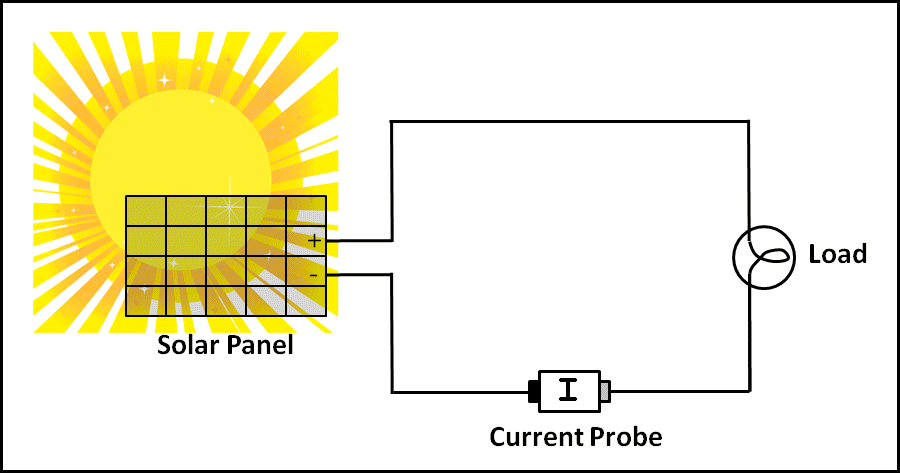
ICIRCUIT SOLAR PANEL SERIES
The same held true with 24V systems.īecause charging was the only game in town, the needs of the batteries dictated how many cells inside the PV should be wired in series and or parallel, so that under most weather conditions the solar modules would work to charge the battery(s). When you had a 12V battery to charge you would use a 12V module, end of story. This nomenclature worked really well because most systems had 12V or 24V battery banks. You would NOT expect to see this number listed on a PV module’s specification sheet and sticker. Nominal voltage is the voltage that is used as a classification method, as a carry-over from the days when battery systems were the only things going. You can reference the chart to find typical VMP values for different types of crystalline modules. The VMP of a module generally works out to be 0.5 volts per cell connected in series within the module. The result should give you or power at the maximum power point, the same as the module’s nameplate wattage. The rated wattage of a PV module can be confirmed in calculations by multiplying the VMP of the module by the current at max power (IMP). It is not uncommon for a load or a battery bank to draw down the VMP of a module or array to a few volts lower than VMP while the system is in operation. It is important to note that this voltage is not easily measured, and is also not related to system performance per se.

VMP is at the place of the bend on an I-V curve where the greatest power output of the module is. You would expect to see this number listed on a modules specification sheet and sticker. Voltage at maximum power is the voltage that occurs when the module is connected to a load and is operating at its peak performance output under standard test conditions (STC). You can reference the chart below to find typical VOC values for different types of crystalline PV modules. This voltage is used when testing modules fresh out of the box and used later when doing temperature-corrected VOC calculations in system design.

You would expect to see this number listed on a PV module’s specification sheet and sticker. Voltage at open circuit is the voltage that is read with a voltmeter or multimeter when the module is not connected to any load.
ICIRCUIT SOLAR PANEL FULL
Though it is promising, this technology is still far from realizing its full prospect. Organic solar cells (OSCs) have developed progressively in efficiency over the last two decades.


 0 kommentar(er)
